

The 30-to-36 metric ton excavator class—led by the Komatsu PC300-8 and PC350-8—represents the heavy-production workhorse of earthmoving, quarrying, and civil infrastructure. At the core of these machines sits the 8.3-liter Komatsu SAA6D114E-3 engine (co-developed and architecturally aligned with the Cummins QSC8.3 / ISC platform), utilizing a high-pressure common-rail (HPCR) fuel injection system operating at peak pressures exceeding 1,600 bar (23,200 psi).
When high-pressure fuel delivery degrades, the symptoms are immediate and costly: extended cranking, sudden engine shutdown under hydraulic stall load, severe derates (Limp Home mode), elevated fuel consumption, or diagnostic codes flashing across the Komatsu machine monitor. However, misdiagnosing high-pressure common rail issues frequently leads to premature, unnecessary replacement of costly high-pressure pumps and complete injector sets.
This technical engineering guide provides field technicians, heavy equipment mechanics, and fleet maintenance managers with a rigorous, methodical diagnostic sequence for the Komatsu SAA6D114E-3 fuel system. From low-pressure supply verification to dynamic rail pressure monitoring, injector return flow testing, and feed tube torque specs, follow this sequence before condemning components.
---1. Technical Specifications: SAA6D114E-3 Fuel Injection Architecture
The Komatsu SAA6D114E-3 HPCR system is an electronically controlled, high-pressure direct injection layout engineered to meet EPA Tier 3 / EU Stage IIIA emissions standards. Below are the verified technical parameters and OEM cross-reference mappings for this platform:
| Parameter / Component | Engineering Specification / Identification |
|---|---|
| Engine Platform | Komatsu SAA6D114E-3 (8.27L / 8.3L, 6-Cylinder In-line, Turbocharged, Air-to-Air Intercooled) |
| Cummins Base Architecture | Cummins QSC8.3 / ISC Common Rail Engine Platform |
| High-Pressure Pump Architecture | Bosch CP3.3 NH Heavy-Duty High-Pressure Radial Plunger Pump with Integrated Gear Lift Pump |
| OEM Pump Part Numbers | Komatsu 6745-71-1170, Cummins 4954200, 3973228, 4921431 |
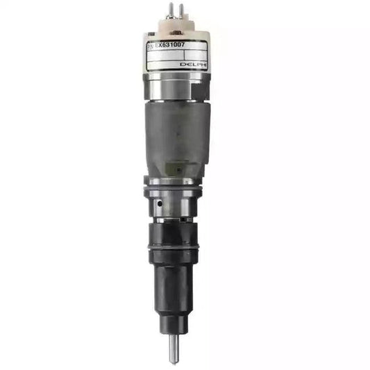
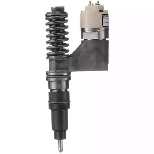
| Common Rail Injector Type | Bosch CRIN2 (Common Rail Injector Commercial / Heavy-Duty) with High-Pressure Feed Tube Connection |
| OEM Injector Part Numbers | Komatsu 6745-12-3100, 6745-12-3101, 6745-12-3102, Cummins 5263308, 4939061, Bosch 0445120236 |
| Fuel Rail Maximum Operating Pressure | 1,600 bar nominal (relief valve set between 1,750 – 1,850 bar) |
| Low-Pressure Gear Lift Pump Pressure | 0.8 to 1.5 bar (11.6 – 21.7 psi) at cranking; 3.0 to 5.0 bar (43.5 – 72.5 psi) at rated speed |
2. Machine & Equipment Compatibility Matrix
The SAA6D114E-3 engine is widely deployed across Komatsu heavy machinery. While the engine block and architecture remain consistent, fuel mapping, injector nozzle flow rates, and mounting flanges vary by equipment arrangement.
| Machine Type | Models Affected | Engine Model | Compatible Primary Injector |
|---|---|---|---|
| Hydraulic Excavators | Komatsu PC300-8, PC300LC-8, PC350-8, PC350LC-8, PC300HD-8 | SAA6D114E-3 | 6745-12-3100 / 0445120236 |
| Wheel Loaders | Komatsu WA380-6 | SAA6D114E-3 | 6745-12-3100 / 0445120236 |
| Motor Graders | Komatsu GD655-5, GD675-5 | SAA6D114E-3 | 6745-12-3100 / 0445120236 |
| Industrial / Generator Sets | Cummins QSC8.3 Industrial Tier 3 / Stage IIIA | QSC8.3 | 0445120272 / Cummins 4940589 |
Important Note on Generation Compatibility: Do not interchange injectors or fuel pumps between the earlier Tier 2 mechanical/CAPS systems (PC300-7 with SA6D114E-2) and the Dash-8 Tier 3 HPCR system (PC300-8 with SAA6D114E-3). Furthermore, Tier 4 Interim / Tier 4 Final Dash-10 and Dash-11 machines (SAA6D114E-5 / SAA6D114E-6) utilize altered nozzle tip angles and distinct Bosch CRIN3 common-rail hardware that are strictly non-interchangeable. Always verify the Engine Serial Number (ESN) on the engine data plate before ordering.
---3. Common Diagnostic Trouble Codes (DTCs) on Komatsu Monitor & J1939
When fuel delivery deviates from ECM commanded parameters, the Komatsu cab monitor displays machine fault codes. These correlate directly with standard SAE J1939 fault codes accessible via diagnostic scan tools:
- CA2249 (SAE J1939 SPN 157 FMI 1 / P0087) – Fuel Rail Pressure Abnormally Low: The ECM detects actual rail pressure is significantly lower than commanded pressure for more than a calibrated threshold (typically 250+ bar deviation under load or inability to reach 250 bar cranking threshold). Triggers an immediate engine derate or stall.
- CA559 (SAE J1939 SPN 157 FMI 18 / P0087) – Rail Pressure Drop Below Operable Limit: Indicates progressive rail pressure loss during active operation, commonly caused by restricted fuel filters or excessive injector dynamic return leakage.
- CA449 (SAE J1939 SPN 157 FMI 0 / P0088) – Fuel Rail Pressure Abnormally High: Rail pressure has exceeded the maximum operating threshold (typically above 1,750 bar). Typically indicates a seized or electrically shorted Fuel Control Actuator (FCA/IMV) or a restricted pump return line.
- CA271 / CA272 (SAE J1939 SPN 1347 FMI 3/4 / P0251) – High-Pressure Pump Metering Valve (IMV/FCA) Circuit Error: Open circuit, short to power, or short to ground detected in the harness leading to the Bosch CP3 suction control valve.
4. Systematic Diagnostic Sequence: Upstream Checks Before Condemning Hardware
In the field, over 60% of common-rail pumps and injectors replaced on PC300-8 excavators are later found to be fully functional on a test bench. Component failure was merely the symptom of upstream supply starvation or aeration. Follow this logical 4-step sequence:
Step 1: Low-Pressure Fuel Supply and Vacuum Testing
- Tank Breather & Fuel Quality: Inspect the fuel tank cap vent. A clogged breather creates a partial vacuum in the fuel tank as fuel level drops, starving the transfer pump. Inspect fuel for water, emulsion, or microbial growth.
- Pre-Filter & Water Separator (10-Micron): Inspect the primary water separator bowl for sediment. Ensure the manual hand priming pump seals tightly and does not ingest air when depressed.
- Suction Line Restriction Test: Install a vacuum gauge between the primary filter and the gear lift pump inlet. Under full engine load (hydraulic relief stall), vacuum must not exceed 6 to 8 in. Hg (20 to 27 kPa). A vacuum reading above 10 in. Hg indicates a pinched fuel line, clogged tank pick-up screen, or collapsed suction hose.
-
Lift Pump Delivery Pressure: Tee a 0–10 bar pressure gauge into the secondary fuel filter head. Measure low-pressure delivery:
- During engine cranking: Minimum 0.8 to 1.2 bar (11.6 to 17.4 psi).
- At low idle (800 RPM): 2.5 to 3.5 bar (36 to 50 psi).
- At high idle / full load: 4.0 to 5.5 bar (58 to 80 psi).
Step 2: Bosch CP3 Fuel Control Actuator (FCA / IMV) Verification
The Bosch CP3 pump on the SAA6D114E-3 utilizes a normally-open Fuel Control Actuator (also referred to as an Inlet Metering Valve or PCV). With zero current supplied, the valve is fully open, directing maximum fuel charge into the pumping chambers.
- Resistance Measurement: Disconnect the two-pin harness connector at the FCA. Measure coil resistance across the terminals using a calibrated multimeter. Standard specification at 20°C (68°F) is 2.5 to 3.5 Ohms. An open circuit (∞) or low resistance (<1.5 Ohms) confirms an internal solenoid failure.
- Unplug Test: Disconnect the FCA connector and attempt to crank the engine. Because the valve is normally open, rail pressure should spike rapidly toward maximum relief pressure (1,600+ bar). If rail pressure fails to rise with the FCA unplugged, the valve may be mechanically seized shut or the pump plungers are heavily scored.
5. High-Pressure Component Testing: Injector Leak-Off & Rail Relief
If low-pressure supply and FCA electrical checks are satisfactory but code CA2249 / P0087 persists, the high-pressure loop is either failing to generate pressure or suffering from massive internal pressure leakage.
Pressure Limiter (Relief Valve) Inspection
The mechanical pressure limiter valve is threaded into the end of the common rail. It serves as a safety rupture valve to prevent catastrophic overpressurization.
- Disconnect the fuel return pipe from the rail relief valve and cap the line fitting.
- Route a clear plastic hose from the relief valve discharge port into a clean catch bottle.
- Crank the engine for 10 seconds or run the machine at idle.
- Pass Criteria: There should be zero leakage (dry port) or at most a few occasional drops. If fuel flows continuously from the relief valve during cranking or idle, the internal spring or seat has eroded. The valve has popped and must be replaced.
Injector Return Flow (Leak-Off) Comparative Test
Excessive internal leakage past the injector control valve is the #1 cause of extended cranking and low rail pressure derates on the Komatsu SAA6D114E-3.
- Disconnect the common injector return manifold from the cylinder head.
- Connect individual graduated test vials or hoses to each cylinder's return port using an approved heavy-duty common-rail test kit.
- Start the engine and run at low idle for exactly 2 minutes (or crank for 15 seconds if non-starting).
- Measure fuel volume returned per cylinder:
- Standard Service Limit: Return volume must not exceed 20 to 25 mL per minute per injector at idle.
- Comparative Ratio: Any individual injector returning more than 30% above the average of the other cylinders indicates excessive control valve seat wear. That cylinder is bleeding rail pressure directly into the return circuit, triggering CA2249.
For a detailed walkthrough of common-rail leak-off testing procedures and tools, consult our engineering guide on Diesel Injector Leak-Off Testing.
---CRITICAL ENGINEERING SAFETY WARNING: HIGH-PRESSURE FLUID HAZARD
The Komatsu SAA6D114E-3 common-rail system operates at hydraulic pressures up to 1,600 bar (23,200 psi), with rail relief spikes exceeding 1,800 bar. A pinhole jet of diesel fuel at this pressure easily penetrates standard shop gloves, skin, and underlying subcutaneous tissue, causing severe, permanent fluid injection injuries, gangrene, and potential amputation.
- Never loosen or crack high-pressure fuel lines while the engine is running or cranking to bleed air. Modern common-rail systems bleed automatically through return circuits.
- Wait a minimum of 10 minutes after key-off for accumulator residual pressure to bleed down completely before breaking any fuel connection. Verify zero rail pressure via the machine service monitor or a diagnostic gauge.
- Always wear ballistic safety glasses, face shields, and heavy leather work gloves during fuel system inspections. Use cardboard or wood—never bare hands—to check for suspected fine leaks.
6. Clean-Room Installation Standards & Feed Tube Torque Specifications
Bosch CRIN2 injectors installed in the SAA6D114E-3 cylinder head do not connect directly to high-pressure lines. Instead, fuel transfers through an intermediate high-pressure feed tube (quill tube) that seats into the side of the injector body. Incorrect installation sequence or torque is the single leading cause of fuel dilution in engine oil and persistent rail leaks.
| Fastener / Step | Torque Specification | Critical Assembly Rule |
|---|---|---|
| Step 1: Injector Hold-Down Clamp Bolt | Initial Snug: 8 N·m (71 in-lb) | Ensure copper combustion seal is brand new. Do not fully torque yet; the injector must retain slight alignment freedom. |
| Step 2: High-Pressure Feed Tube Retaining Nut | Initial Seating: 15 N·m (11 ft-lb) | Lubricate the feed tube O-ring with clean engine oil. Hand-thread to ensure the tip aligns into the injector inlet orifice without cross-threading. |
| Step 3: Injector Hold-Down Clamp Bolt (Final) | Final Torque: 38 N·m (28 ft-lb) | Torque the hold-down clamp bolt to final specification, locking the injector down against the copper washer. |
| Step 4: High-Pressure Feed Tube Retaining Nut (Final) | Final Torque: 50 N·m (37 ft-lb) | Apply final torque to the feed tube retaining nut to create the metal-to-metal high-pressure seal against the injector body. |
| High-Pressure Injection Pipe Line Nuts | Torque: 30 N·m (22 ft-lb) | Use a calibrated flare-nut crowfoot wrench. Never bend or force high-pressure lines into alignment. |
Feed Tube Replacement Protocol: Whenever an injector is replaced, thoroughly inspect the feed tube tip. If the spherical sealing face exhibits scoring, erosion, or fret marks, replace the feed tube. Reusing a damaged feed tube will cause pressurized fuel to leak past the cylinder head seal directly into the rocker cavity, rapidly diluting engine oil with diesel and risking crankshaft bearing failure.
---7. OEM Verification & FuelPartsPro Component Solutions
When diagnostic testing confirms hardware failure on your Komatsu PC300-8 or PC350-8 excavator, installing factory-calibrated, high-durability replacement parts ensures OEM-spec fuel atomization, prompt starting, and maximum engine life.
FuelPartsPro provides direct-fit, precision-tested fuel injection components for the Komatsu SAA6D114E-3 platform:
- Common Rail Fuel Injectors: Komatsu 6745-12-3100 / 6745-12-3101 / 6745-12-3102 / Bosch 0445120236 Injector. Fully calibrated and tested to strict OEM flow, response time, and return-rate tolerances.
- High-Pressure Common Rail Pump: Komatsu 6745-71-1170 / Cummins ISC8.3 & QSC8.3 Bosch CP3 Fuel Injection Pump. Complete with integrated gear pump and factory-tested Fuel Control Actuator.
- Related Heavy Equipment Applications: Also view our 0445120305 / 6746-11-3100 Injector for Komatsu SAA6D114 & Cummins QSL and our 0445120272 Injector for Cummins QSC8.3 Industrial Engines.
- Related Technical Guides: Review our diagnostic guide for the smaller 6.7L platform: Komatsu PC200-8 SAA6D107E-1 Fuel System Guide or troubleshoot rail pressure faults with our P0087 Diagnostic Guide and SPN 157 Diagnostic Guide.
Need Fitment Verification? Diesel engine configurations vary across serial number breaks and international emissions tiers. Before ordering, send our engineering team a clear photo of your engine data plate (showing the Komatsu Engine Serial Number and Arrangement / CPL number) or old pump/injector part tags. We guarantee 100% fitment accuracy before your machine leaves the bay.