

Overview
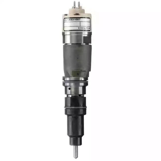
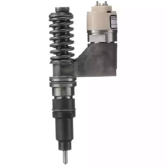
The 2644N209 (also listed as 2644N209/24) is a mechanical rotary distributor fuel injection pump designed for the Perkins 1104C-44 diesel engine. This pump is a Delphi/CAV DPS-series unit that meters and pressurizes fuel for delivery to each cylinder in firing order sequence. Unlike common rail systems, the 1104C-44 uses a mechanically timed injection system where the pump directly controls injection pressure and timing — making pump condition critical to engine performance, emissions, and reliability.
1. Part Specifications
- Part Number: 2644N209 / 2644N209/24
- Pump Type: Delphi DPS Series Rotary Distributor Injection Pump
- Engine: Perkins 1104C-44 (4-cylinder, 4.4L diesel)
- Emission Tier: Tier 2 / Stage II compliant
- Injection System: Mechanically timed, distributor-type (non-common rail)
- Drive: Gear-driven from engine front cover
- Governor Type: Mechanical all-speed governor
2. Compatible Vehicles & Equipment
The Perkins 1104C-44 engine powered by this pump is used across a wide range of industrial and construction equipment:
- Caterpillar (CAT) Machines — Various CAT compact and mid-size machines using Perkins-sourced 1104C engines, including skid steer loaders and telehandlers
- JCB Equipment — JCB 3CX/4CX backhoe loaders, JCB 530/535 telescopic handlers
- Massey Ferguson Tractors — MF 5400 and 6400 series agricultural tractors
- AGCO / Fendt Tractors — Mid-range tractors using the 1104C-44 platform
- Manitou Telehandlers — MT series telescopic handlers
- Industrial Generators — Stationary and mobile gensets using the Perkins 1104C-44 base engine
- Compressors & Pump Sets — Various industrial power units
Always verify the engine serial number and fuel system code stamped on the pump before ordering. The 1104C-44 was produced in multiple variants; confirm the 2644N209/24 suffix matches your application.
3. Common Fault Codes & Diagnostic Indicators
The 1104C-44 with the 2644N209 pump may be monitored by an ECM (on later electronic variants) or diagnosed mechanically on earlier builds. Common fault indicators include:
- P0216 — Injection Timing Control Circuit Malfunction: On electronically assisted variants, indicates the timing advance solenoid on the pump is not responding correctly to ECM commands.
- P0251 — Injection Pump Fuel Metering Control “A” Malfunction: The fuel metering valve (FMV) or throttle solenoid circuit has an open or short circuit fault.
- P0252 — Injection Pump Fuel Metering Control “A” Range/Performance: The FMV is responding but not achieving the commanded fuel delivery rate — typically caused by internal pump wear or sticking metering valve.
- P0370 / P0371 — Timing Reference High Resolution Signal: Fault in the pump-mounted timing sensor, causing the ECM to lose injection timing reference.
- P1211 — Injection Control Pressure Above/Below Desired: Pump output pressure is outside the expected range for the given operating condition.
- Perkins EST Code 1690 — Fuel System High Pressure: Pump delivery pressure exceeds specification, often caused by a stuck delivery valve or blocked return circuit.
- Perkins EST Code 1691 — Fuel System Low Pressure: Pump cannot achieve minimum delivery pressure; caused by worn plungers, failed transfer pump, or severe fuel contamination.
4. Failure Symptoms & Diagnosis
Symptom 1: Hard Starting / Excessive Cranking Time
Cause: The internal transfer pump (vane pump) has worn and cannot build sufficient priming pressure. Alternatively, the delivery valves may be leaking, allowing fuel to drain back to the tank overnight.
Diagnosis: Check fuel transfer pressure at the pump inlet port using a low-pressure gauge (should be 0.8–1.2 bar at idle). If low, the transfer pump vanes are worn. Also perform a fuel drain-back test: cap the return line and check if the engine starts more easily after priming — if so, a leaking delivery valve is the cause.
Symptom 2: Loss of Power Under Load
Cause: Worn pump plunger and barrel assembly reduces maximum fuel delivery at high load. The governor cannot compensate for the reduced volumetric efficiency.
Diagnosis: Perform a pump flow bench test if available. On-machine, monitor exhaust temperature and smoke. A worn pump typically produces grey/white smoke under load with reduced power. Compare actual vs. rated fuel consumption — a worn pump often shows lower-than-expected fuel consumption despite poor performance.
Symptom 3: Rough Idle & Hunting
Cause: Sticking or worn governor flyweights cause erratic fuel metering at low speed. A partially blocked fuel filter can also cause pressure fluctuations that manifest as idle instability.
Diagnosis: Replace the fuel filter first. If hunting persists, check governor spring tension and flyweight condition. On electronically governed variants, check the FMV solenoid resistance (typically 5–10 ohms) and compare to specification.
Symptom 4: Black Smoke at All Loads
Cause: Over-fueling due to incorrect maximum fuel delivery setting, a stuck-open metering valve, or incorrect injection timing (too advanced).
Diagnosis: Check injection timing using a timing tool or dial gauge on the pump. Verify the timing marks align with the engine TDC mark. If timing is correct, the pump requires bench calibration to reset maximum fuel delivery.
Symptom 5: White Smoke & Misfiring
Cause: Late injection timing or a failed delivery valve allowing fuel dribble into the cylinder during the compression stroke, causing incomplete combustion.
Diagnosis: Retard/advance timing and observe smoke change. If white smoke reduces with timing advance, the pump timing has drifted. Inspect the pump drive gear for wear or a sheared timing key.
5. Replacement Procedure
⚠️ Safety Note: Ensure the engine is cold and the fuel system is depressurized before beginning. Clean the pump and surrounding area thoroughly before removal to prevent contamination.
- Disconnect the battery negative terminal.
- Remove the engine top cover and locate the injection pump on the front-left of the engine block.
- Disconnect all fuel lines (inlet, outlet, return) and cap immediately. Label each line to ensure correct reinstallation.
- Disconnect the throttle linkage and any electrical connectors (timing solenoid, FMV solenoid, stop solenoid).
- Mark the pump flange position relative to the front cover using a scribe or paint pen — this preserves the approximate timing setting.
- Remove the pump drive gear nut and use a gear puller to remove the drive gear. Do not hammer the gear.
- Remove the pump mounting nuts (typically 3) and withdraw the pump from the front cover.
- Install the new 2644N209 pump, aligning the flange to the scribe marks made in Step 5.
- Torque the mounting nuts and drive gear nut to Perkins specification (refer to Perkins 1104C-44 Workshop Manual — typically 25 Nm for mounting nuts, 80–90 Nm for drive gear nut).
- Reconnect all fuel lines, throttle linkage, and electrical connectors.
- Prime the fuel system using the hand primer pump until firm resistance is felt.
- Start the engine and verify injection timing using a timing light or dial gauge. Adjust as necessary.
- Check for fuel leaks and confirm no fault codes are present.
6. Maintenance Tips to Extend Pump Life
- Replace the primary and secondary fuel filters every 500 hours or annually — the DPS pump is highly sensitive to fuel contamination.
- Use a fuel water separator and drain it every 250 hours. Water causes rapid corrosion of the pump’s precision steel components.
- Always use clean, low-sulfur diesel (EN590 or equivalent). Avoid biodiesel blends above B5 unless the pump is specifically approved for higher blends.
- Never run the engine out of fuel — the pump relies on fuel for internal lubrication. Running dry causes immediate wear to the transfer pump vanes and plunger.
- After pump replacement, always re-verify injection timing on a running engine before returning the machine to service.
7. Get the Replacement Part
If your Perkins 1104C-44-powered machine is showing any of the symptoms above, a quality replacement pump is the most reliable solution. Our 2644N209/24 Fuel Injection Pump for Perkins 1104C-44 is built to OEM specifications for correct fit, accurate fuel delivery, and long service life. Order today and get your equipment back to full working condition.