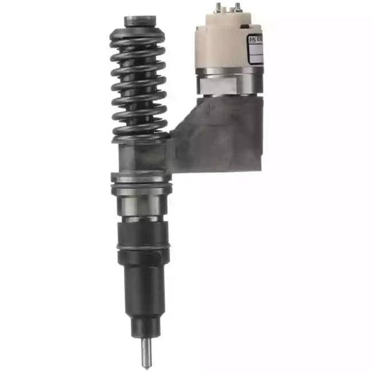


Understanding J1939 DTC SPN 157: Heavy-Duty Fuel Rail Pressure Management
In the heavy-duty commercial vehicle, off-highway construction, and power generation sectors, diagnostic trouble codes are broadcast across the SAE J1939 controller area network (CAN). Unlike light-duty automotive applications that generate standard OBD-II P-codes (such as P0087 or P0088), heavy equipment powered by Cummins, Caterpillar, Komatsu, Detroit Diesel, and John Deere reports common rail fuel pressure issues using Suspect Parameter Number (SPN) 157: Injector Metering Rail 1 Pressure.
When an engine control module (ECM) logs an active SPN 157 fault, operators and technicians typically witness severe performance degradation: immediate engine torque derates (ranging from 25% to 50% power reduction), hydraulic lag during heavy excavation cycles, extended cranking or intermittent no-start conditions, harsh metallic combustion clatter, or sudden engine shutdown under load. Because common rail pressures operate between 300 bar (4,350 psi) at idle and upwards of 1,800 to 2,000 bar (26,000 to 29,000 psi) at full rated load, the ECM enforces strict tolerance envelopes around rail pressure accuracy.
Misinterpreting SPN 157 frequently leads to unnecessary and costly component replacements—such as condemning an expensive high-pressure injection pump when the real problem is a collapsed suction strainer, an aerated low-pressure supply, or an open 5V sensor reference circuit. This guide provides a systematic, step-by-step engineering diagnostic protocol to isolate the exact mechanical, hydraulic, or electrical root cause before replacing major fuel system hardware.
J1939 Failure Mode Identifiers (FMIs) for SPN 157
SPN 157 must always be evaluated in conjunction with its corresponding Failure Mode Identifier (FMI). The FMI indicates whether the failure is electrical (wiring harness, sensor signal) or hydraulic (delivery starvation, excessive back-leakage, mechanical overpressure):
| FMI | Description & Condition | Common Physical Root Causes |
|---|---|---|
| FMI 0 | Data Valid but Above Normal Operational Range (Most Severe) | Stuck-closed Suction Control Valve (SCV/FCA), pinched fuel return line creating hydraulic backpressure, mechanical pressure limiter failed shut. |
| FMI 1 | Data Valid but Below Normal Operational Range (Most Severe) | Severe high-pressure delivery failure, blown Pressure Relief Valve (PRV) discharging to tank, primary fuel starvation, worn high-pressure pump plungers. |
| FMI 2 | Data Erratic, Intermittent, or Incorrect | Intermittent harness wiring chafing, damaged rail pressure sensor pins, loose ground terminal, high electromagnetic interference (EMI) on sensor signal. |
| FMI 3 | Voltage Above Normal or Shorted High (> 4.75V) | Signal wire shorted to 5V sensor supply or battery power, broken sensor return/ground circuit, internally failed rail pressure transducer. |
| FMI 4 | Voltage Below Normal or Shorted Low (< 0.25V) | Signal wire shorted to chassis ground, disconnected sensor harness plug, loss of 5V regulated ECM excitation supply. |
| FMI 16 | Data Valid but Above Normal Operating Range (Moderately Severe) | Actual rail pressure consistently exceeds ECM commanded target by > 15–25 MPa during steady-state or deceleration transients; sluggish SCV/MPROP metering valve response. |
| FMI 18 | Data Valid but Below Normal Operating Range (Moderately Severe) | Equivalent to OBD P0087; fuel rail pressure cannot achieve commanded target under engine load. Plugged primary fuel filter, lift pump restriction, high injector back-leakage. |
Engine Platform & Equipment Compatibility
SPN 157 is widely encountered across Tier 3, Tier 4 Interim, and Tier 4 Final heavy machinery platforms. Always verify the specific engine arrangement, serial number (ESN), and fuel injection system manufacturer before ordering replacement components:
- Cummins Common Rail Platforms: QSB3.3, QSB4.5, QSB6.7, QSC8.3, QSL9, ISX15, and X15. Utilizes Bosch CP3 / CP4 high-pressure pump systems or Cummins High Pressure Injection (HPI-TP / XPI) common rail systems.
- Komatsu Hydraulic Excavators & Wheel Loaders: PC200-8, PC210-8, PC220-8, PC270-8, PC300-8, PC350-8, WA380-6, WA470-6 powered by SAA4D95LE, SAA6D107E-1, SAA6D114E, and SAA6D125E engines. Employs Denso HP3/HP4 or Bosch common rail architectures.
- Caterpillar Heavy Equipment: 320D, 324D, 329D, 336D excavators powered by C6.4, C7, C7.1, C9, and C9.3 ACERT common rail platforms.
- Isuzu Commercial & Industrial Engines: 4HK1, 6HK1, 4JJ1 fitted to Hitachi ZX200-3, ZX240-3, JCB JS200, and Isuzu NPR/NQR commercial trucks with Denso HP3/HP4 common rail systems.
Note: Never assume common rail components are interchangeable across engine displacements or model years. Always verify the manufacturer casting number and engine data plate.
5-Step Step-by-Step Diagnostic Protocol for SPN 157
To avoid misdiagnosis, technicians must follow a structured elimination sequence: isolate electrical faults first, test low-pressure delivery second, verify dynamic high-pressure leakage third, and test pump mechanical output last.
Step 1: Differentiate Circuit Faults vs. Hydraulic Performance
Connect an electronic service diagnostic tool (Cummins INSITE, Caterpillar ET, Komatsu Komtrax/Service Tool, or an SAE J1939 generic scanner). Inspect active versus inactive fault logs:
- If FMI 3 or FMI 4 is active: The fault is strictly electrical. Do not touch high-pressure hydraulic lines or pump assemblies. Proceed directly to Step 2.
- If FMI 0, 1, 16, or 18 is active: The ECM is receiving valid electrical sensor signals, but actual hydraulic rail pressure is out of commanded tolerance. Proceed to Step 3.
Step 2: Electrical Circuit & Sensor Pinout Verification (FMI 3 & 4)
The Rail Pressure Sensor (RPS) is a 3-wire piezoresistive transducer mounted directly on the high-pressure fuel rail. Disconnect the sensor harness connector and perform multimeter back-probe tests with Key-On, Engine-Off (KOEO):
- Pin 1 (5V Supply): Measure voltage between the harness 5V supply pin and engine block ground. It must read 4.95V to 5.05V DC. If reading 0V, inspect harness for an open circuit or internal ECM 5V power supply shutdown.
- Pin 2 (Ground Return): Measure resistance between harness ground pin and chassis ground. Circuit resistance must be under 5.0 Ohms.
- Pin 3 (Signal Voltage): Back-probe the signal wire with the connector plugged in. With 0 bar rail pressure (engine stopped), signal voltage must measure approximately 0.50V DC (±0.05V). At maximum rated rail pressure (1,800+ bar), signal voltage climbs to approximately 4.50V DC. If signal voltage remains frozen at 5.0V or 0V while disconnected/connected, the transducer diaphragm is internally damaged.
Step 3: Low-Pressure Fuel Delivery & Aeration Checks
Common rail high-pressure pumps rely entirely on a stable, air-free supply of clean diesel from the low-pressure circuit:
- Filter Restriction & Vacuum Test: Install a vacuum gauge between the primary fuel filter/water separator and the transfer pump inlet. Under full engine load, inlet vacuum must not exceed 10 to 12 in.Hg (34 to 40 kPa). A higher vacuum reading indicates plugged fuel filters, a blocked tank pickup tube strainer, or collapsed suction hose.
- Air Ingress Inspection: Install a clear fluoropolymer sight tube into the fuel pump inlet line. Crank the engine and observe fuel clarity. Any streaming micro-bubbles indicate air being drawn into the suction line via loose fittings, water-in-fuel drain valves, or cracked primer pump diaphragms. Aerated fuel compresses inside the high-pressure plungers, causing catastrophic pressure drop (SPN 157 FMI 18).
- Supply Pump Delivery Pressure: Verify gear-type or electric lift pump output pressure. Typical common rail supply pressure must measure between 0.35 MPa and 0.55 MPa (50 to 80 psi) at cranking speeds.
Step 4: High-Pressure Leakage & Pressure Limiter Valve (PRV) Test
If low-pressure supply meets specification but SPN 157 FMI 18 persists, the system is suffering from high-pressure leakage:
- Pressure Relief Valve (PRV) Bypass Check: The mechanical PRV on the end of the fuel rail protects the system from burst overpressure. Disconnect the low-pressure fuel return pipe from the PRV outlet and route a temporary transparent hose into an empty graduated container. Crank or idle the engine. Under normal conditions below 1,600 bar, zero fuel should discharge from the PRV. If fuel drips or pours out during cranking or idle, the internal spring or ball seat is eroded, leaking rail pressure directly back to tank. Replace the PRV immediately.
- Injector Static & Dynamic Leak-Off Test: Excessive internal control chamber wear inside common rail injectors permits high-pressure fuel to dump into the injector return circuit, starving the rail. For detailed testing specs and isolation procedures, refer to our comprehensive Diesel Injector Leak-Off Test Guide.
Step 5: High-Pressure Pump & Metering Valve Evaluation
If fuel delivery is clean and the rail/injectors are not bypassing fuel:
- Suction Control Valve (SCV / FCA / MPROP) Inspection: The inlet metering solenoid modulates fuel volume entering the high-pressure pumping elements. Check coil resistance (typically 2.0 to 4.5 Ohms at 20°C). Inspect the internal metering spool for sticky varnish, dark lacquering, or metal debris. For detailed electrical and duty-cycle diagnostics, consult our P0251 Fuel Metering Control Diagnosis guide.
- Pump Output & Dead-Head Cranking Test: Using an electronic diagnostic scan tool, monitor actual rail pressure while cranking with the injectors electronically disabled. A healthy HPCR pump must build at least 250 to 300 bar (3,600 to 4,350 psi) within 3 to 5 seconds of cranking. If the pump fails to achieve 250 bar despite positive low-pressure fuel feed, internal plunger scoring or worn delivery valves prevent hydraulic pressure generation.
CRITICAL ENGINEERING SAFETY WARNING: HIGH-PRESSURE FLUID INJECTION
DANGER: Common rail fuel injection systems operate under extreme hydraulic pressures exceeding 2,000 bar (29,000 psi).
Fluid escaping at this velocity can easily penetrate industrial work gloves, denim, and human skin. Fluid injection injuries cause severe deep-tissue necrosis, chemical gangrene, and can lead to permanent amputation or fatality. Never place your hands, fingers, or skin near high-pressure fittings, rails, or injectors while the engine is running or cranking.
- Always shut down the engine and wait a minimum of 10 to 15 minutes for residual rail pressure to bleed down.
- Confirm with an electronic diagnostic scan tool that measured fuel rail pressure reads 0 bar (0 psi) before loosening any high-pressure fitting.
- Always wear ANSI Z87.1 approved eye protection and heavy-duty nitrile/leather protective gloves during fuel system service.
- Never \"crack\" high-pressure injector lines to bleed air on an electronically controlled common rail engine. Bleeding must be accomplished strictly through the low-pressure primer pump circuit.
Installation, Priming & Adaptation Procedures
When replacing a fuel injection pump, rail pressure transducer, or injector set to resolve SPN 157, precision installation practices are mandatory:
- Surgical Cleanliness: Thoroughly degrease and wash all surrounding components before opening any line. Immediately cap every exposed fitting and rail port with clean plastic plugs. Microscopic abrasive dust (above 2 to 5 microns) will score precision valve spools within minutes of initial startup.
- Torque to Factory Specification: Over-tightening common rail flare nuts or pressure sensor threads causes microscopic bore ovality, leading to high-pressure leaks and cracked flare shoulders. Tighten injector line nuts strictly with a calibrated crowfoot torque wrench to OEM values (typically 28 to 35 N·m).
- Low-Pressure Circuit Bleeding: Manually operate the primer pump while venting the primary filter air bleed screw until clear, bubble-free diesel flows without foam. Lock down all bleed screws before engaging the starter motor.
- ECM Calibration & Adaptation Learning: After installing a new high-pressure pump or SCV/MPROP valve, use diagnostic software to perform the \"Fuel Pump Delivery Learning Reset\" or \"SCV Initialization Routine\". When replacing fuel injectors, always program each injector's unique calibration code (QR trim code) into the ECM to ensure balanced cylinder-by-cylinder fueling.
Precision Common Rail Components & Fitment Support
FuelPartsPro stocks OEM-grade, precision-calibrated common rail components engineered to withstand continuous heavy-duty industrial operating cycles. Explore our direct replacement products below:
- 0445020070 / 6271-71-1110 High-Pressure Fuel Pump (Cummins QSB3.3 & Komatsu SAA4D95LE)
- 6745-71-1170 / 6745-71-1180 High-Pressure Fuel Pump (Cummins ISC/ISL & Komatsu SAA6D114)
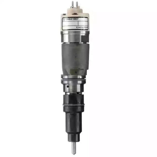
- 0445120059 / 6754-11-3011 Common Rail Fuel Injector (Cummins / Komatsu SAA6D107)
- 0445120236 / 6745-12-3100 Common Rail Fuel Injector (Komatsu SAA6D114E)
- 294000-2600 / 294000-0039 High-Pressure Fuel Pump (Isuzu 4HK1)
For related fault code troubleshooting and testing procedures, explore our technical library:
- P0087 Fuel Rail Pressure Too Low Diagnostic Guide
- P0088 Fuel Rail Pressure Too High Diagnostic Guide
- P0093 Large Fuel System Leak Diagnostic Guide
Need Fitment Verification? Diesel common rail systems vary significantly across equipment serial numbers. Send clear photos of your engine data plate, machine serial tag, or old component casting numbers to our engineering support team for guaranteed fitment verification prior to shipment.